Summary/Issue Description
The purpose of this document is to provide the steps to set up implicit communications using tag data links via Ethernet/IP between two NJ or NX machine automation controllers using Network Configurator.
Root Cause
Example Using Network Configurator Required – Set up implicit communications using tag data links via Ethernet/IP between two NJ or NX machine automation controllers using Network Configurator.
Solution
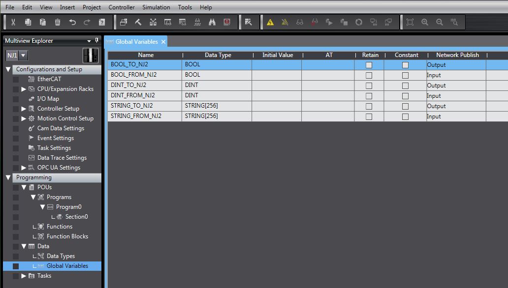
Create Variables in Sysmac Studio
Create the variables to be shared between the controllers in global variables. Set Network Publish to Output for data to be sent to another controller or Input for data to be read from another controller. In this example the names of the controllers are NJ1 and NJ2.
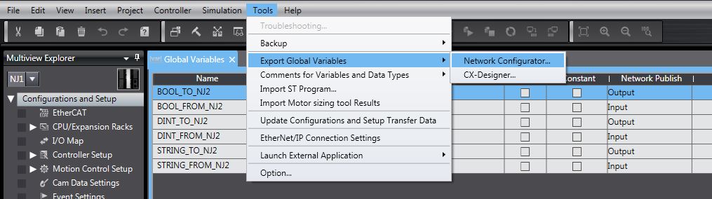
Export Variables to Network Configurator
After creating the variables choose Export Global Variables to Network Configurator under the tools menu. This will create a csv file that will be imported into Network Configurator. Creating and exporting the variables needs to be repeated for each controller.
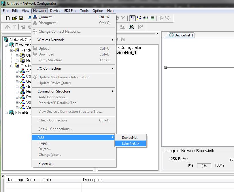
Network Configurator – Add Ethernet/IP Network
Open Network Configurator for Ethernet/IP. When you open Network Configurator you may have a DeviceNet network in your project by default. If so, add an Ethernet/IP network under the Network tab.
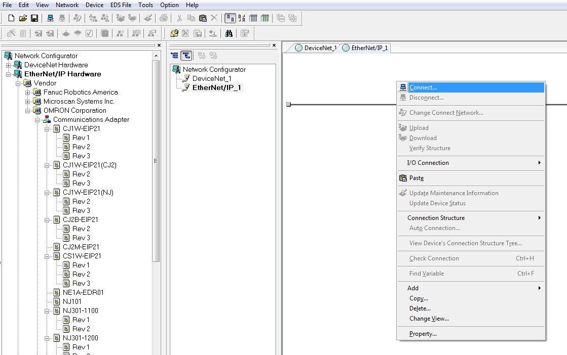
Network Configurator – Add Devices
(If able to connect to the network, skip to Upload Network on page 6)
Find the model number of the NJ or NX controller and drag it into the Ethernet/IP network.

Network Configurator – Change Node Address
Change the node address to the IP address of controller’s built in Ethernet port by right clicking the controller. In this example the setting of the controller’s IP address was transferred to the controller using Sysmac Studio and then the node address was set accordingly in Network Configurator.

Network Configurator – Upload Network
If you are connected to the network you can upload the network rather than creating it manually. First, Select the Interface for how you will connect to the network under the Option tab.

Then right click in the network windows and select Connect.
Select which Ethernet port of your PC you will be using to connect.

Then select OK

The online status is indicated by the blue circle. Once online, right click in the network window and select upload.

Select the IP address of the devices you want to upload to the network.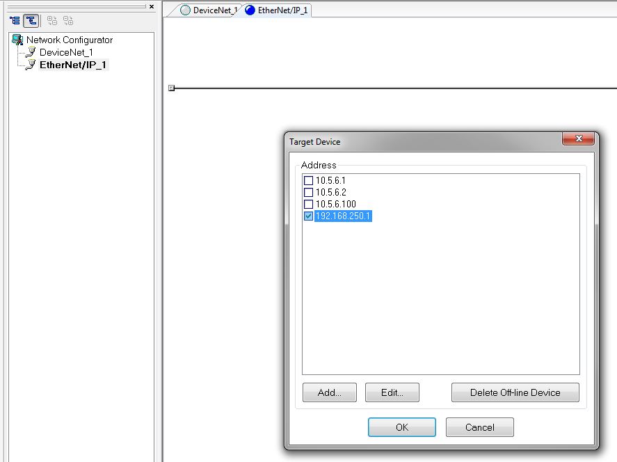
Network Configurator – Edit Parameters
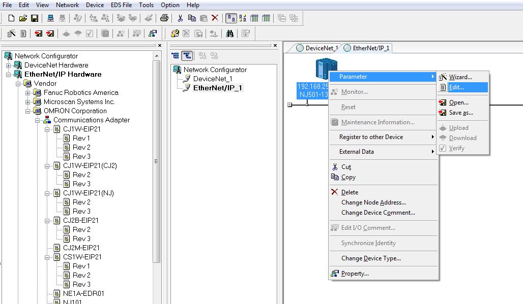
Right click the controller and select Parameter Edit.
Network Configurator – Import Tag Sets
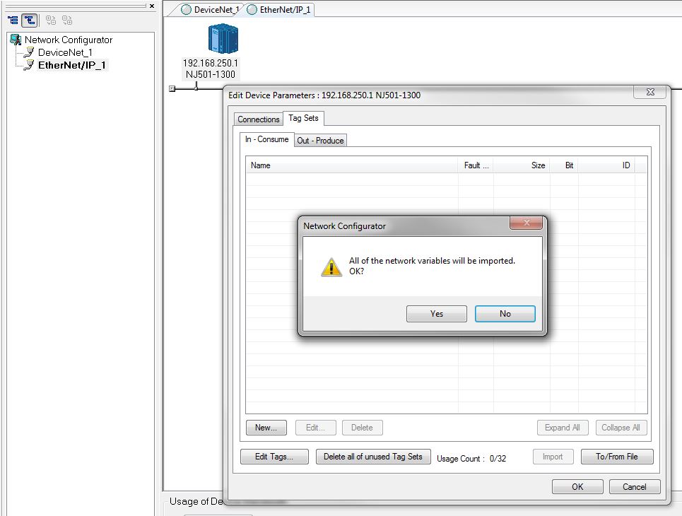
Select To/From File then Import from File. Then select the csv file that was exported with Sysmac Studio for this controller.


You will then be prompted to import all network variables that were exported by the Sysmac Studio project. If you select No you can then choose which variables you want to import.

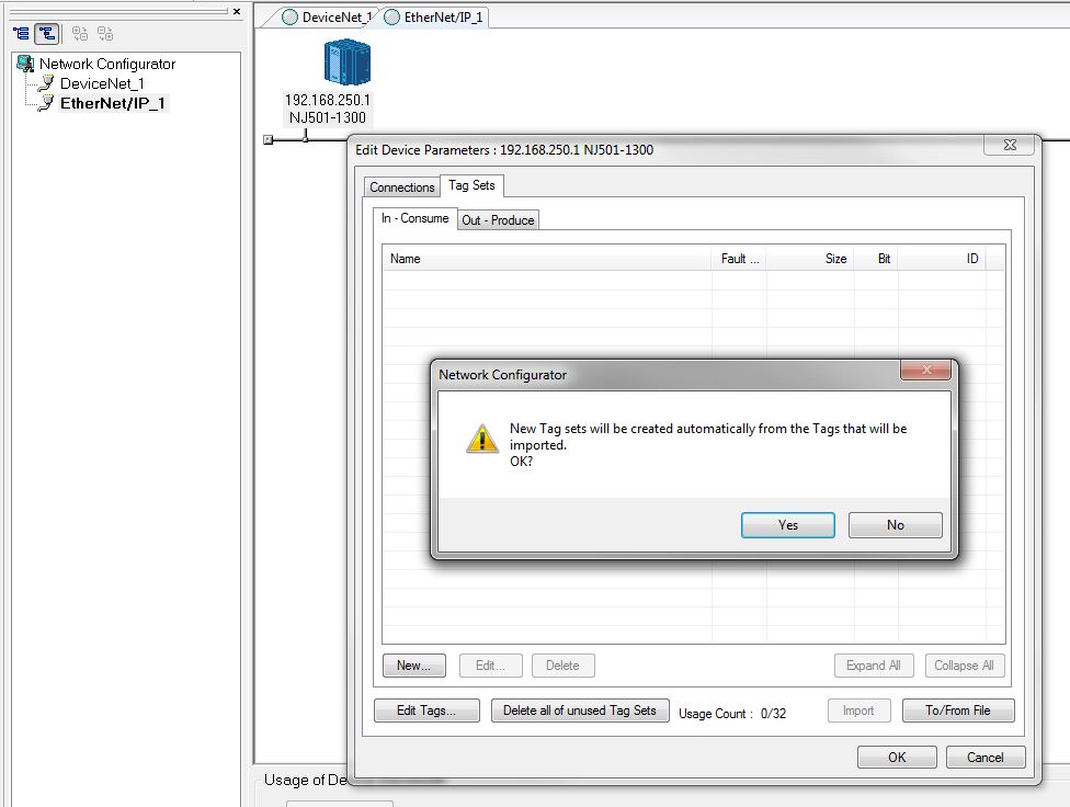
Select Yes to automatically create the tag sets.
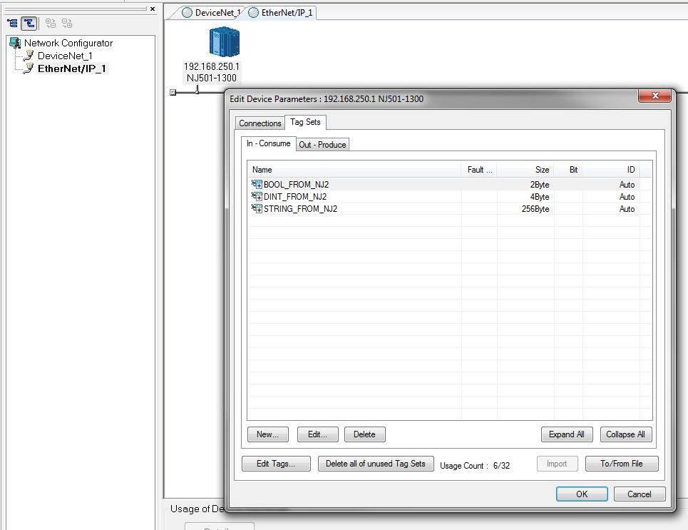
You can then see the Input and Output data that was previously created in Sysmac Studio.

Network Configurator – Connections
The steps to create the tag sets need to be repeated for each controller. Then, in the connections tab, select a device from the Unregistered Device List and click the icon to move it to the Registered Device List.

Then double click the device to edit connections.

For each variable, select the tag set name in the Input Tag Set drop down. In this example the tag set names are the same as the variable names.

Then select the corresponding variable in the output tag set drop down for the target device and click Regist to register the connection. Repeat this for each variable, then click Close.

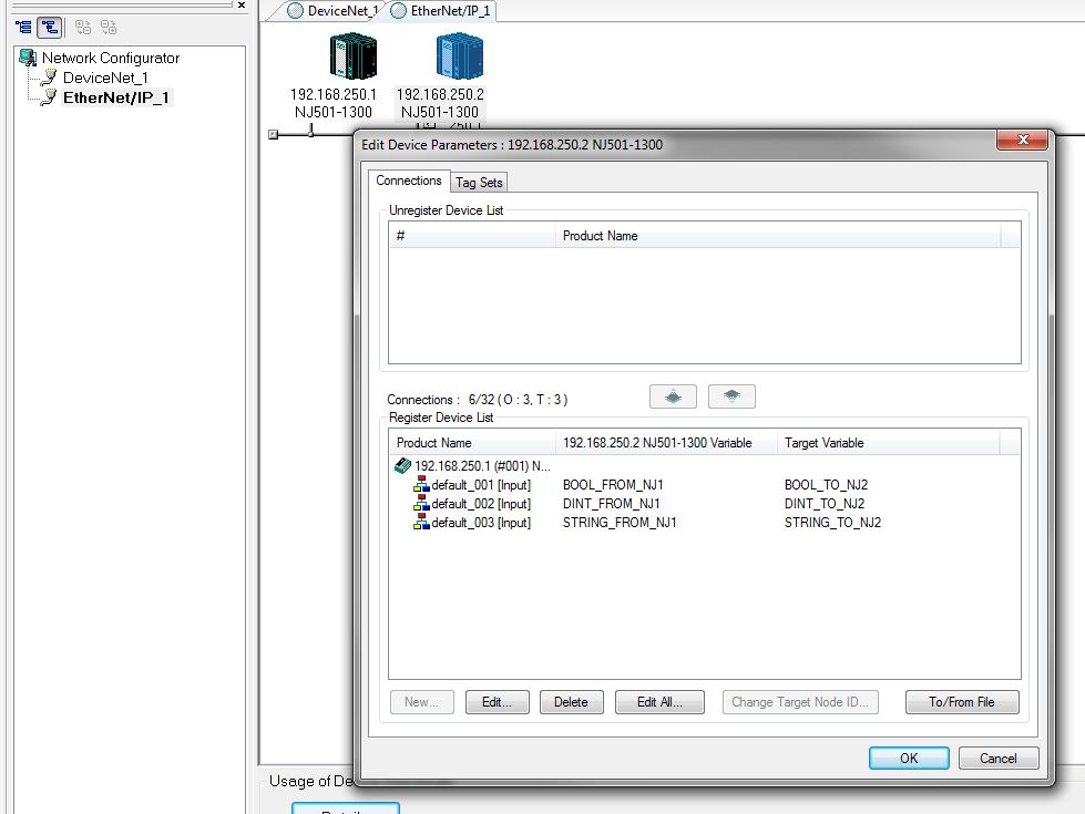
The connections are now displayed. Click OK, then repeat the steps for the other controller.

After repeating the steps for controller 2, the connections are now created in each controller. The built in Ethernet/IP port of the NJ and NX1P2 controllers support up to 32 connections. Notice that 6 connections are utilized in this example. Refer to the Structures section on page 25 for more information on how to make more efficient utilization of connections.
Network Configurator – Download
When connected to the network, right click each device to download its parameters. Refer to the Upload Network section beginning on page 6 for additional details on connecting to the network.

Download with Current mode can be used to transfer the tag data link connection settings without taking the controller out of run mode.

Sysmac Studio – Watch Tab
You can then test communications in Sysmac Studio using the watch tab. You can drag variables from the global variables list into the watch tab. 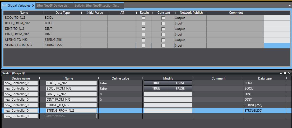
Sysmac Studio – Connection Settings
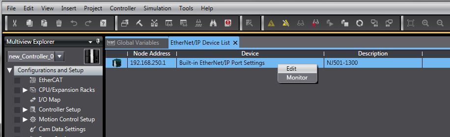
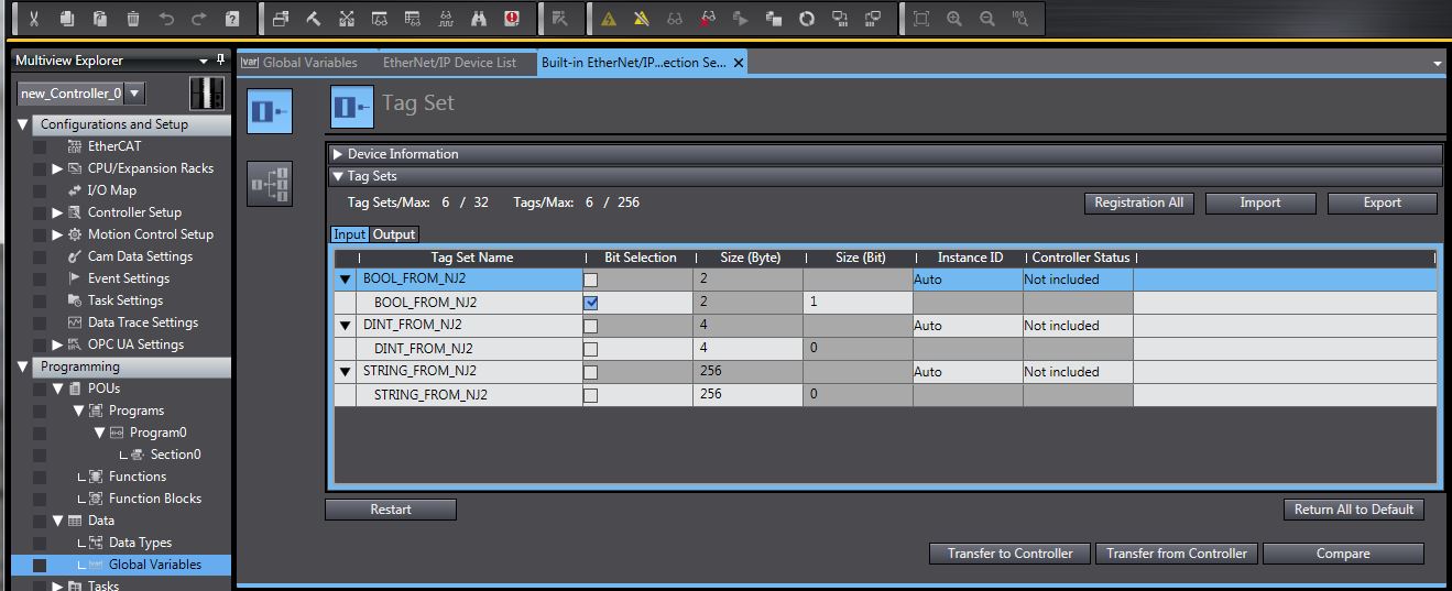
To save the tag data link connection settings in the Sysmac Studio project select Ethernet/IP connection settings in the Tools menu.

Then right click and select Edit.
Then select Transfer from Controller. You can then see the input and output tag set data and the connection settings and save this in the Sysmac Studio project. The built in Ethernet/IP port of the NJ and NX1P2 controllers support up to 32 connections. Notice that 6 connections are utilized in this example. Refer to the Structures section on page 25 for more information on how to make more efficient utilization of connections.

Sysmac Studio – Structures
The built in Ethernet/IP port of the NJ and NX1P2 controllers support up to 32 connections. To make better utilization of the number of the number connections supported, multiple variables of different data types can be contained within a user defined structure.
In this is example one structure is created for the output data and one for the input data. The content of these structures is the same data that was configured in the previous example.
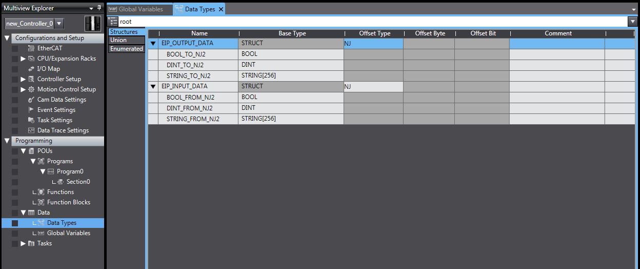
After the structures are created simply create one output variable and one input variable with the structure name as the data type.

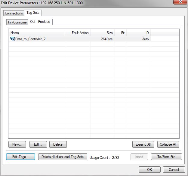
After exporting the variables from Sysmac Studio (see page 2) and importing them into Network Configurator (see page 10) the same amount of data from the previous example now only uses 2 of the available 32 connections (one connection for input data and one for output data).
The size of the tag set in this example (same as the size of the structure created in Sysmac Studio) is 264 Bytes. For the NJ and NX1P2 built in Ethernet/IP port, the maximum amount of data per connection is 600 Bytes. Therefore, when using a structure for implicit communication via tag data links with the built in Ethernet/IP port of the NJ or NX1P2 the size of the structure must not exceed 600 Bytes.

If greater than 32 connections is required a CJ1W-EIP21 module v2.1 or later can be mounted to an NJ controller, providing an additional 256 connections with a maximum size of 1444 bytes per connection. The NJ controller supports up to four(4) CJ1W-EIP21 modules (not supported by NX1P2).
Date/Revision History
First review 9/30/2025 V1.0
Author:
Ed Gallagher – Technical Support Supervisor
References
Sysmac Studio Version 1 Operation Manual
NJ/NX-series CPU Unit Built-in EtherNet/IP Port User's Manual
Was this article helpful?
That’s Great!
Thank you for your feedback
Sorry! We couldn't be helpful
Thank you for your feedback
Feedback sent
We appreciate your effort and will try to fix the article